Tuesday, November 15, 2011

A basic programme to read and write PWM signal


#include
int pin = 7;
int val  = 0;
Servo myservo;
unsigned long duration;

void setup()
{
  pinMode(pin, INPUT);
  //pinMode(9, OUTPUT);
  myservo.attach(9);
}

void loop()
{
  duration = pulseIn(pin, HIGH);
  duration = map(duration,1160,1780,0,179);
  myservo.write(duration);
}

Wednesday, September 7, 2011

Accelerometer And Gyroscope..

Q: What's the difference between a gyro and an accelerometer? Do I need both?

An accelerometer measures acceleration. A 3-axis accelerometer will tell you the orientation of a stationary platform relative to earth's surface, once that platform starts moving, however, things get more complicated. If the platform is in free-fall, it will show zero acceleration. If it is accelerating in a particular direction, that acceleration will simply be added to whatever acceleration is being provided by gravity, and you will not be able to distinguish. A 3-axis accelerometer in an aircraft in a properly coordinated turn with a 60 degree angle of bank, for instance, will show 2 G "vertical" acceleration in the aircraft, despite the fact that the aircraft is tilted 60 degrees relative to the horizon. So, accelerometers alone can't be used to keep in an aircraft in a particular orientation.

A gyro measures rate of rotation around a particular axis. If a gyro is used to measure the rate of rotation around the aircraft roll axis, it will measure a non-zero value as long as the aircraft is rolling, but measure zero if the roll stops. So, a roll gyro in an aircraft in a coordinated turn with a 60 degree bank will be measure a rate of zero, same as an aircraft flying straight and level. You can approximate the current roll angle by integrating the roll rate over time, but you can't do so without some error creeping in. Just to make life more interesting, gyros drift with time, so additional error will accumulate over a period of minutes or even seconds, and eventually, you'll have a totally inaccurate idea of your current roll angle relative to the horizon. So, gyros alone can't be used to keep in an aircraft in a particular orientation.

So, in a nutshell: Accelerometers are right in the long term but wrong (noisy) in the short term. Gyros are right in the short term but wrong (drifiting) in the long term. You need both--each to calibrate the other--to be right all the time.

But even that only works in for pitch and roll. For yaw, which is orthogonal to gravity, the accelerometers can't help you, so you need something else to correct your drifting yaw gyro. That's either magnetometers (electronic compasses, which are vulnerable to magnetic interference and intertial forces) or GPS.

GPS has a relatively slow update rate (1 to 10 Hz) and is subject to short term errors. It is possible to use GPS alone to keep a very stable and slow flying airframe on a particular ground track on a calm day.

An inertial measurement unit (IMU) combines (fuses) information from two or more sensors, such as gyros, accelerometers, magnetometer, and/or GPS, to determine orientation and velocity vector relative to the earth. The computations are fairly complex, and special filtering is often required to eliminate the measurement noise these silicon devices are subject to, so a "low cost" off-the-shelf IMU with decent specs can easily cost $1000 to $5000 US.

Infra-red horizon sensing "copilots" are inexpensive and work fairly well as long as they have a clear view of the horizon. Unfortunately, mountains, clouds, haze, buildings, etc., will confuse them. [Chris here: I think IR stabalization is more effective than people give it credit for, and is actually rarely confused in standard usage. Both Paparazzi and AttoPilot are built on it, and they work great. See this interview for more.]

In the end, the techniques used to stabilize a UAV will be very much dependent on the intended use, budget, and how comfortable one might be working with sensor fusion, Kalman filters, etc.


Source:DIY DRones

Sunday, May 29, 2011

Thursday, May 12, 2011

Wednesday, April 20, 2011

2 Testing the quadrotor @ IES IPS Academy


See how powerful this Quadrotor "dragon" is? So we tied the threads to this machine.
Again need ur good wishes my friends to make this machine a more stabilised one......

Testing the Quadrotor in IPS Academy


Testing the quadrotor @ the IPS Academy.....The quadrotor understands our commands but still have some problems of balancing so ,we tied four threads so that it will not hit someone and itself with something.

Threads got stressed when it tries to lift up but still we increased the speed only upto 60-70% so as to minimize the risk factor of breaking of any of the components of the quadrotor.

Hoping that very soon we will be able to train this dragon!.......a wonderful and a powerful dragon......Always need ur best wishes....

Training the Dragon!!!!!!!!!!!!!!!

Good morning,
Yes it is very true that now our quadrotor is able to understand us and follow our instructions.But still its very tough for that Quadrotor to stabilise in the mid-air.

So we are now checking the Gyroscope signals and output angles to make it a stabilized one...

This quadrotor is really very fast and it lifts up with very high thrust.Testing and stabilizing this Quadrotor is like training the dragon......

Monday, April 18, 2011

Our Quadrotor Hovering


Assembling the blades of Quadrotor helicopter


Our quadrotor hovering on the platform of Technido.In the above video we have used only near about 30% of the total speed of our quadrotor ,so it is only hovering.The another reason for not increasing the speed of the quadrotor at once is that our quadrotor is not balanced right now.So if we had increased the speed ,the machine could have turned upside down and fell on the ground.Now Balancing this quadrotor is our next big and challenging task.

We are very happy because today we not only was able to hover this quad ,but also we were able to rotate it clockwise and counterclockwise.

Again we would like to thanks Mr. Siddharth dev sir for ,the time they given to us and the project.

Thanks a lot God for all the ideas!!!!!!!!!!!!!

Our quadrotor rotating clockwise and Counter Clockwise


Our quadrotor helicopter trying to hover and rotating clockwise and counter-clockwise according to our instructions....

Sunday, April 17, 2011

Controling all four motors of the quadrotor with the wireless remote

Gaurav(sky blue tshirt) ,Mayank(centre),Lokesh(chequed shirt) making the connections of wires of our quadrotor helicopter for the testing of the Quadrotor @ the Technido Indore.


Our dude the Gaurav Gupta "Joy Lobo" showing the quadrotor helicopter....

Lokesh "The programmer" is here with lovely attitude showing the quadrotor helicopter...

Lokendra checking the signals @ CRO,the most important equipment for the testing of the signals that we transmitt and receive.

Gaurav ,Mayank(me) and Lokesh showing our quadrotor helicopter


Lokendra looking @ our quadrotor helicopter and seems very happy as this new Quadrotor the latest model started working very well.....


Thanks a lot God and all the friends for the good wishes because of which the project started working.
We are very Thankful to all people who have guided us directly or indirectly for this Quadrotor helicopter.

Hoping very best for the next steps

Mayank Gupta

Sunday, April 10, 2011

Saturday, March 12, 2011

Analysis of PWM signals on CRO coming out of the receiver of Quadrotor Helicopter


The receiver module of our quadrotor helicopter containing six channels ,i.e. we can transmit and receive six signals simultaneously.The Pwm signals comes out of these receiver module which changes according to the movement of the joystick(analog stick) available in the transmitter.If we move the stick of channel 1 in the transmitter then we get change in the signals of the first channel of the receiver,same is the case with other channels of the receiver.......

Tramsmitter-receiver module.This trasmitter trasmits signals @2.4 Ghz.The range of this trasmitter is more than 100 metres ,cant say more than that because we have checked only upto 100 meters.The range could be much more than that.It is a four channel trasmitter.This transmitter works on GFSK technique with FM modulation.

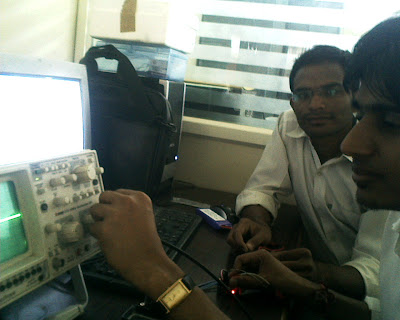
In the above picture Lokendra Tomar giving power to the receiver module by connecting that to ESC .Receiver is not directly connected to battery because the power requirement of receiver is very less and it is given by inbuilt BEC of the ESC (Electronic speed controller),so ESC is connected to the battery and then receiver is connected to the ESC (for circuit/connection diagram :look @ the previous post typical connection diagram of receiver and ESC).After the conection one of the channel output of the receiver is given to the input of the CRO.

Lokesh parmar then calibrated the CRO according to the signal we were receiving on the CRO.CRO was self tested by Joshi sir(Lab technician),before we started working.After Changing the time divisions and the amplitude and shifting the wave on CRO,we got the waveform that we were trying to look for.Its an On-off pulse with an maximum voltage of about 3.5 volts and the On(High) timing of the pulse is 20 ms and Off(low) time 4 ms.So the frequency of pulse is approximately 40 Hz..
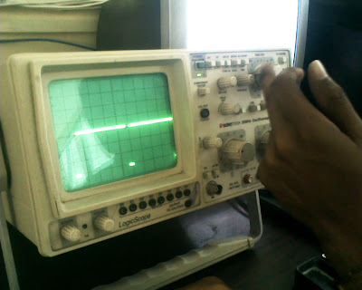
Look @ the anove pulseon CRO, how smooth and clear it is.Off(low) time in the above pulse is very low but even then you can easily observe that.

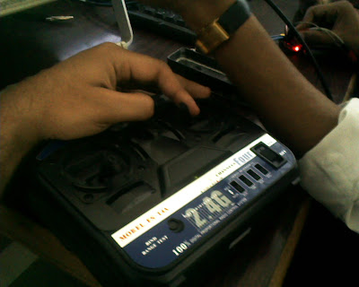
On moving the Analog Stick(joystick ) of channel 1 ,the pulses of channel 1 changes.When we move the analog stick upward ,the width of the ON time increase in accordance to the movement of stick,when we move analog stick downward the OFF width of the pulse increases.But the overall width of the pulse remained the same.


we looking @ the varying pulse on moving the analog stick and analysing the signals and calculating the results.

After the whole testing was done we had tea as always ,beacause
"Yaar ab itti testing ke baad ek chai to banti hai.................. "

This whole testing was done in the lab of our college IES-IPS Academy.Sorry but i forgot what was the name of the lab,the only thing we need was a CRO.

Mayank Gupta

Friday, March 11, 2011

Hardware Part:Mounting brushless motor on carbon fiber rods.....


The above photo is showing screws and nuts used for the mounting of the brushless motors,and a rubber is used to suppress the vibrations


The above picture is showing the motor mounted on the carbon fiber rod....with the help of aluminium plates

The picture is showing the rubber between the carbon fiber rod and the motor.Rubber is used to supress the vibrations and to give proper strength to carbon fiber rod ,so that we can easily tighten the screws without breaking the carbon fiber rods


Motor is mounted on carbon fiber rods with the supports of aluminium plates connected which we drilled according to the threads and holes available in the brushless motors and a rubber is inserted between the motor and the carbon fiber rods ,so that carbon fiber rod do not break and vibrations could be reduced.

Carbon fiber rods are fragile in nature perpendicular to the threads but it is very tough and give great strength along the threads.

It is not advised to drill a whole directly into carbon fiber rods because it could just spread the carbon fiber rod from there ,and will be of no use .Same is the case when u r cutting it .So we should be very careful while cutting the rods as this is very costly .

The another thing that u can use to drill into carbon fiber rod is , just use some hot pin point thing ,in this way your carbon fiber rod will not spread out and you can make a hole into that.

Monday, February 14, 2011

our old model